 . Both the Application and Devices need to be added afterwards. Define Devices first if known or define Application(s) first if they determine what Devices are needed.
This tutorial should give you an overview of how to work with 4DIAC. We will take the toggle Flip-flop, T-Flip-flop, as our task and use it as a running example for the different solution approaches. The tutorial starts with modeling an IEC 61499 Application using available FBs. For this application we will specify a test System consisting of two Devices, after the mapping of the Application's parts to the Resources we will test it. The T-Flip-Flop can also be implemented as a Basic, a Composite, or a Service Interface Function Block and used within the Application, whereas the steps for Function Block Development have to be considered.
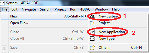
Task of the Flip-Flop Tutorial:We need a System to put our Application into. To create a System with an empty Application you have to go to the System Perspective  . Both the Application and Devices need to be added afterwards. Define Devices first if known or define Application(s) first if they determine what Devices are needed.
 button.
 .
.
results in

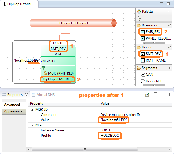
Devices and their Resources have to be created to map the Applications to. Communication Segments link Devices together. 4DIAC supports launching IEC 61499 Applications running in a Resource running FORTE for PLC/PC or a Resource running FBRT for HMI. For the Flip-Flop Application we have one Device running FORTE (POSIX) and simulating an embedded Device. To set up the Device perform the following steps:
 if not already open.
The Application contains the functionality a specific System or System component is supposed to perform. In 4DIAC-IDE create a new Application under File/New/New Application. If you click on your Application name you will just see an empty window.
Double click on the Application name to open the Application. Existing Function Block types can be dragged into an Application by Type Navigator. If the Type Navigator is not shown within the System perspective open it with Window/Show View/Other/Type Management/Type Navigator. Inside the Type Navigator view Function Blocks are grouped according to the Systems they belong to and inside the System folder in categories and sub-categories.
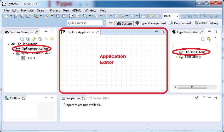
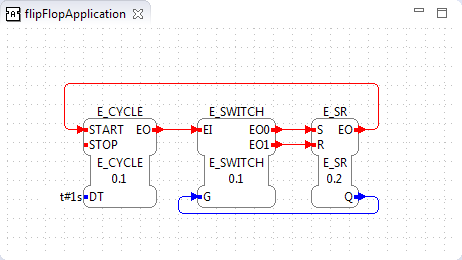
Check these categories for one existing Function Block that does the whole task. We look for a XOR or Set/Reset, that includes timing and output. Under Events find E_RS. Since it doesn't toggle the state, is event-driven and not time activated, and also no other FB can be found providing the desired functionality, an Application will be created by a group of existing Function Blocks. Now we need to add Function Blocks to build the Application. You can use the edit field within the Type Navigator to search for a specific type and drag and drop the result into the Application Editor. We need three event Function Blocks that can be used to build the T Flip-Flop:
Connectors are used to control the order of data and event flow. To activate an event action both the Data and event must have been received by the FB. In Type Navigator View double click on the Function Block to see its event and data connections. Start to connect your Function Blocks with those that need to be initialized by INITO to next INIT until you start the event chain of the Application. To make a connection click and hold on the event name. A rounded rectangle should appear. Drag the connector from one output variable to the desired input variable. The forbidden circle under the arrow will disappear when it is over the desired input variable name. Release the mouse to connect. Follow your connectors through the Application, whereas one output event may be input to multiple Function Blocks. Check that all input events are triggered or you know why they are not needed. An input event may come from multiple FBs but be careful with multiple event inputs, that they are not sent for same reasons and cause events to grow exponentially.
The data needs to have inputs as well, either a constant value of its type or a connector input from a data output variable of another Function Block. For constant values type the desired value next to the data input variable. Valid time values are T#<time length><time measurement>, like 5 seconds as T#5s, T#5000ms.
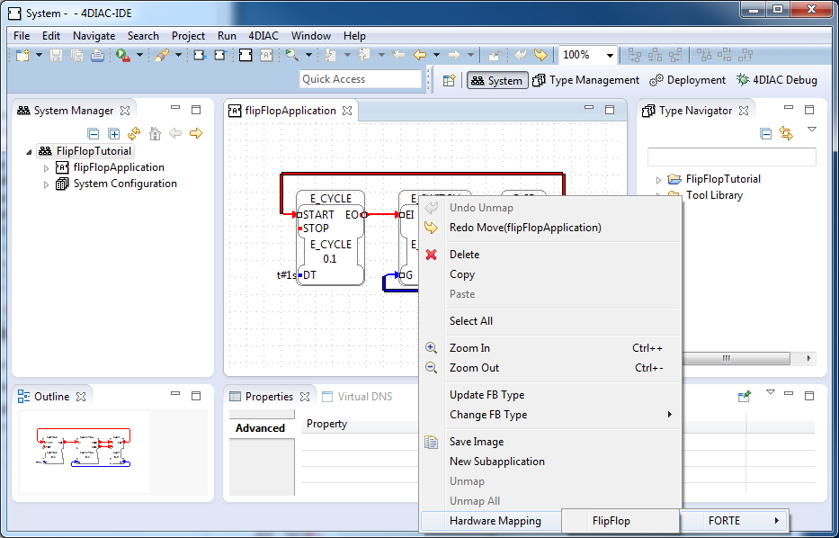
Now we need to map our Application on the Device, we created earlier, to run it. Right click and choose Hardware Mapping/FORTE/FlipFlop. To show that the Function Block is mapped to a Device the Function Block will become colored in the same color the Device was given in System Configuration and a green diamond will appear at top left of the Function Block.
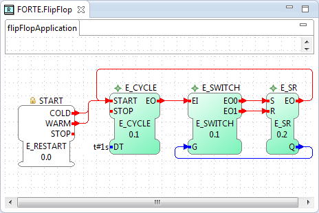
Switch to the Resource within the System Manager by double clicking on the desired Resource. Resources are found in your System under the System Configuration node within any of the displayed Devices. Within the editor you now see your Application mapped to this Resource. Connect the COLD and the WARM start events of the E_RESTART Function Block to your Application's first event, which is E_CYCLE.START event. The COLD event is send on system startup whereas the WARM starts from last known state and values.
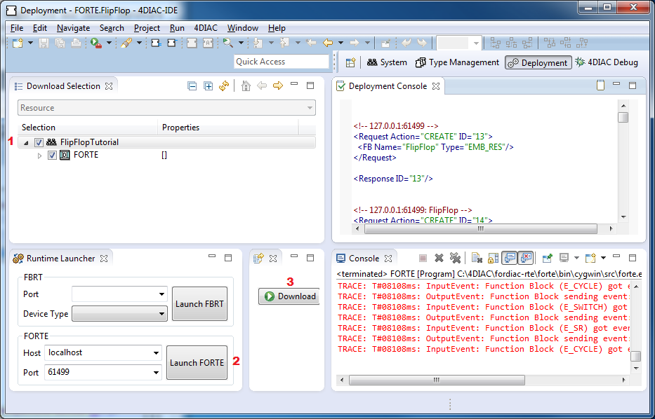
Switch to the Deployment perspective  and check your System's name. Launch FORTE either by the Launch FORTE button or by manually starting the forte.exe. If you use the Launch FORTE button consider that you have to set the properties. Within the Deployment Console you see the download commands and within the console you will the outputs of FORTE.
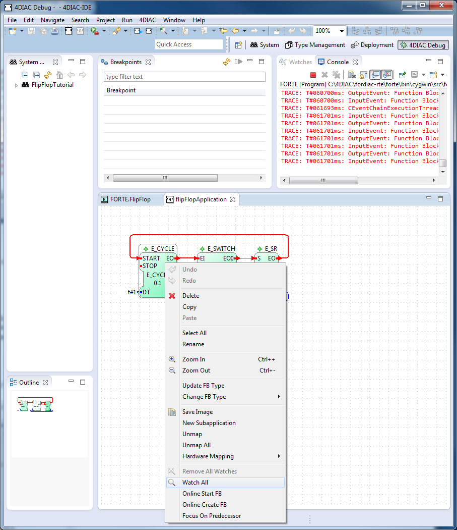
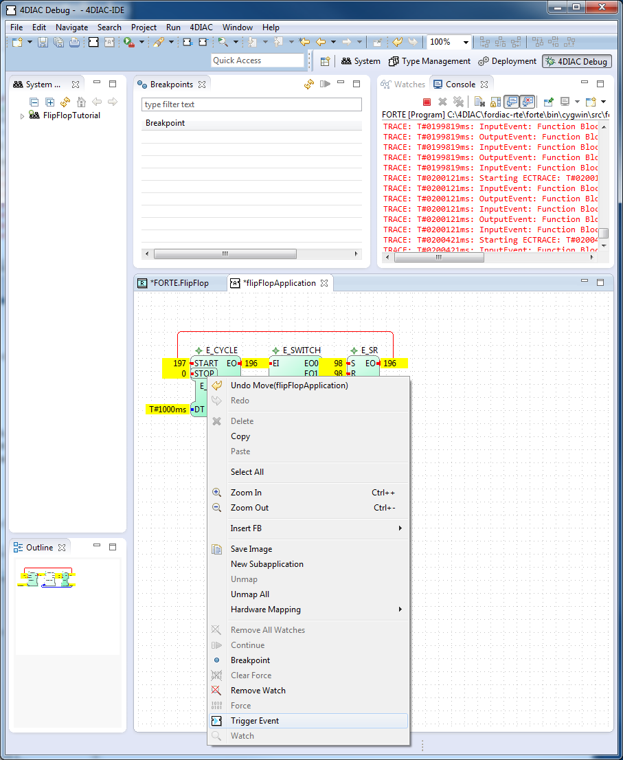
To observe the outputs of your Application you can use 4DIAC's Monitoring functionality. Right click on the System and choose Monitor System. Then switch to the 4DIAC Debug perspective  and open the corresponding Application.
Within this view, it is possible to select the elements which should be monitored. This is done with a right mouse click on the specified element. Either the whole Function Block by Watch All, or a single interface element of a Function Block by Watch can be selected. After that the current values of the selected elements will be displayed in the engineering environment next to the interface elements as depicted as well as in the Watches view.
Additionally, it is possible to trigger events. Therefore, it is necessary to select Trigger Event menu from the context menu of an event interface element.
The values of a Function Block input data can be overwritten by the force command form the context menu. The next time, the function block is executed the forced value will be used. The old value will be visualized in brackets.